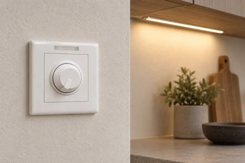
An LED fitting can work well at full output and become unstable when dimmed. It may flash near the bottom of the range, start at a higher level than expected or behave differently when several units share a control. These symptoms are reasons to evaluate the complete light-source, driver and dimmer combination before ordering a room’s worth of fittings.
The word “dimmable” establishes an intention, not universal compatibility. This guide helps a buyer collect useful evidence and organize a qualified sample review. Electrical faults, supply issues and mains connections belong with a qualified professional; the steps here concern product selection and documented behavior.
Describe the symptom before choosing a replacement
Record whether instability occurs at full output, while changing levels, only at the minimum setting or immediately after switching on. Note whether every fitting behaves the same way and whether the symptom changes with the number of connected units. A short video can help communicate the sequence, although camera bands alone do not establish a flicker measurement.
Record the fixture, driver and dimmer model numbers, revisions and any configured settings. If the project uses an external controller, include it. The same fixture family may contain several drivers with different control methods, so a generic catalog name leaves a significant gap. Do not select replacement parts until the actual assembly has been identified.
Confirm the control method
Ask whether the driver supports phase-cut, analog or digital control, and obtain the exact interface description. Phase-cut variants may specify leading-edge or trailing-edge behavior. Analog descriptions may differ in minimum level or off behavior. A digital interface needs the intended controller and configuration. Similar-looking control terminals or a familiar dimmer faceplate do not establish interchangeability.
The Lutron controlling-LEDs white paper explains that dimming performance depends on how the driver responds to the control. Use manufacturer compatibility evidence for the exact combination whenever available. If a project requires a specific protocol or certification, verify that claim for the exact product rather than inferring it from an interface label.
Separate visible symptoms from measured modulation
The US Department of Energy flicker overview distinguishes changes in output over time from the visual effects they can produce. A light that appears steady during a brief look is not necessarily free of modulation, and a camera can respond differently from a person.
For projects with a defined flicker requirement, ask for a report using the specified metrics and operating points. A statement such as “flicker free” is difficult to compare without a method and test condition. Include the dimmed scenes in the evidence request. A report at full output does not establish what happens at the lowest required setting.
Use a symptom-to-evidence table
| Observation | Useful next evidence | Buyer’s decision |
|---|---|---|
| Flicker only near minimum | Approved dimming range and trim guidance | Can the required scene be achieved? |
| Flashing when starting low | Start-up behavior at the selected scene | Does the sample restart predictably? |
| Different behavior with more fittings | Tested quantity and load limits | Is the intended group supported? |
| Noise during dimming | Exact compatibility and sample review | Is the acoustic result acceptable? |
| Camera banding | Defined camera setup and modulation report | Does it suit recording requirements? |
Treat the table as an evidence-gathering tool, not an electrical diagnosis. If the fitting is unstable without a dimming control or changes unexpectedly during normal operation, the responsible professional should assess the system before further product trials.
A worked low-end compatibility example
Assume a hospitality project requires a low ambient scene around 5% of measured full light output. In a qualified sample test, a hypothetical fitting starts reliably at 12% but becomes unstable below 8%. Its full-output behavior is satisfactory. The requested scene and the sample’s demonstrated stable range therefore do not match.
The team could revise the scene if the design allows it, or choose and test a different driver/control combination. Raising low-end trim might avoid the unstable region, but it would not create the originally requested 5% scene. These numbers describe an invented decision example. Slider position, control command and measured light-output percentage should be recorded separately because they need not be equal.
Check quantity, startup and restart behavior
A compatibility test should represent the smallest and largest intended control groups. Record connected quantity, exact products and the relevant manufacturer limits. A control’s incandescent wattage rating is not enough to describe every LED load. Ask the designer to review the applicable LED rating and any limits related to the driver behavior.
Test transitions between normal scenes, starting from the lowest approved scene and returning after a controlled power interruption under qualified supervision. Document any delay, pop-on, abrupt step or disagreement between fittings. If a venue expects a remembered scene, confirm that behavior explicitly. Do not assume it from the fact that the control retains its own command.
Approve the whole dimming assembly
Before sample testing, define the required minimum level, off behavior, fade quality, acoustic expectations and any filming use. Request the driver data sheet, control compatibility statement, setup guidance and test reports relevant to those requirements. Retain the permitted settings together with the sample outcome so they can be reproduced at commissioning.
A supplier should identify any component change between the approved sample and production. Even an equivalent-looking driver can change the result. If control behavior is customized, discuss application software customization. For electrical load matching, read constant current versus constant voltage; for a controlled release, use sample approval.
Frequently asked questions
Why does a dimmable LED flicker on my existing dimmer?
The exact driver and control may not support the same method or stable range. Identify both models and obtain compatibility guidance. Have a qualified professional assess the installation if the behavior could involve an electrical fault.
Can low-end trim fix every flicker problem?
No. It can restrict a supported control to a stable range in some combinations, but it does not repair an incompatible interface or establish a lower light level. Follow model-specific guidance and verify the required scene.
Is a phone camera a reliable flicker test?
It is useful for documenting visible behavior and filming problems, but exposure, frame rate and rolling shutter affect the result. Use an appropriate measurement method when a specification requires quantified flicker performance.