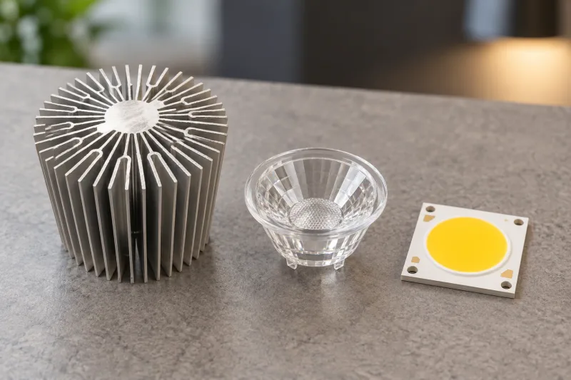
A custom fixture’s heat sink and optic are often chosen in separate conversations. That can leave the team with a lens that fits the drawing but conflicts with a thermal part, or a compact housing that looks right while leaving too little space for heat transfer. The useful starting point is the complete light engine: LED source, board, interface, heat sink, optic and enclosure.
This guide helps buyers organize those decisions before a working sample is approved. It explains the information an engineer needs, the limits of simple calculations and the observations a sample should record. It does not claim a universal wattage capacity for a heat sink or a guaranteed beam from an unnamed lens.
Define the source and operating point
Identify the exact LED package or module, board dimensions, electrical operating point and intended output. A change in module or current can alter both heat and optical behavior. Keep the selected part revision visible in the drawing and bill of materials so a later substitution receives a coordinated review.
State where the fixture will operate: open air, a sealed housing, a ceiling cavity or a display cabinet. Include expected ambient conditions, permitted mounting orientation and available clearance. “Indoor” is not enough to define thermal conditions. A source inside a compact enclosed fitting can experience a very different environment from the same source on an open laboratory bench.
Review the complete heat path
Heat must pass through more than the visible metal fins. Cree LED’s thermal-management application note describes the path from LED junction through the board, thermal interface and heat sink to the surrounding environment. A large heat sink cannot compensate for a poorly defined contact interface elsewhere in that path.
Ask for the board construction, interface material, contact-area requirements and assembly controls. The engineer should specify what matters for flatness, mounting and repeatability. A prototype assembled by hand with an unrecorded interface can produce a result that production does not reproduce. Retain those process details with the approved thermal design.
Use a thermal estimate as a planning tool
Assume an engineer estimates 12 W of heat from a selected module at its operating point. Assume the preliminary thermal model uses a 40°C ambient temperature and a total junction-to-ambient thermal resistance of 4°C/W. The simplified estimate is 40 + (12 × 4) = 88°C at the junction.
If the total resistance becomes 6°C/W because of a different interface or enclosure arrangement, the estimate rises to 112°C. These are hypothetical inputs, not measured results or allowable limits for any product. The engineer must compare the estimate with the exact LED data sheet and confirm the model using an appropriate temperature measurement and validated method. Electrical input should not automatically be treated as the heat figure without a reviewed basis.
Match the optic to the actual LED
A lens designed around one emitting surface may behave differently with another. Request the compatible LED list, optical model, mechanical drawing and proposed beam data. Check source position, holder geometry and clearance. A nominal beam angle is useful, but it does not fully describe the center intensity, spill or appearance of the beam edge.
LEDiL’s lens catalog identifies optical families with particular package and application compatibility. Use the same level of specificity in your custom inquiry. An attractive lens photograph is a starting reference; the chosen LED/optic combination and test conditions should define the result approved for production.
Compare optical and thermal choices together
| Decision | Optical question | Thermal or mechanical question |
|---|---|---|
| Narrow beam | Is the target fully covered? | Does the chosen holder fit the heat-sink layout? |
| Wide beam | Is spill or visible glare acceptable? | Does the larger optic restrict airflow or assembly? |
| Diffused output | Are brightness and appearance suitable? | Is the diffuser material within its temperature limits? |
| Compact housing | Can the required distribution fit? | Is the complete heat path validated? |
| Sealed enclosure | Are cover effects included in photometry? | Are temperatures checked in the closed assembly? |
A wider beam is not inherently better or worse; it serves a different task. Likewise, more metal is not a complete thermal specification. Ask reviewers to connect each change to the intended light distribution, enclosure constraints and measured operating conditions.
Validate the finished enclosure
Measure and evaluate the assembled fixture in the intended orientation and at a relevant operating condition. Record ambient temperature, input setting, enclosure state and identified measurement locations. The LED manufacturer’s specified reference point and calculation method should guide any junction-temperature assessment. Touching the exterior or taking a casual infrared image does not establish the LED junction temperature.
Perform the optical review with the final cover, diffuser and finish installed. A shiny internal surface or protective window can change distribution and visible artifacts. Compare the sample with the agreed target plane and viewing positions. If the project requires photometric evidence, request data for the completed configuration rather than transferring a bare lens’s catalog result to the assembled fixture.
Create a coordinated sample checklist
Send the LED reference and data sheet, electrical point, board and housing drawings, target distribution, ambient conditions and size constraints. Request a proposed thermal interface, heat-sink design, lens/holder combination and validation plan. In the sample record, include measured conditions, optical observations, part identifiers and any deviations from the brief.
Agree which changes require a new review. A different board, interface, finish, lens material or source position can affect the result even if the outer appearance remains similar. Compare lenses and reflectors and send the heat-sink requirements with the complete assembly drawing. Coordinate development through light source solutions. The guides to driver selection and sample approval complete the specification path.
Frequently asked questions
Can I select a heat sink only from LED wattage?
No. The source’s heat estimate, full thermal path, ambient conditions, enclosure and orientation all matter. Have the engineer evaluate the exact assembly and compare validated temperatures with the component limits.
Will the same lens work with any LED package?
Do not assume that. Source size and position affect the distribution. Request documented compatibility and evaluate the chosen combination with the final holder and cover.
Is a cooler-looking external housing proof of a safe LED temperature?
No. The relevant internal temperature depends on the heat path and measurement method. Use the manufacturer’s reference data and an appropriate engineering assessment instead of judging by touch or appearance.